0
0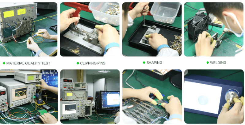
How to test fiber optic module?
As networks grow and technologies advance, many manufacturers of fiber optic components appear in the market and try to get their share of the network world. Since these manufacturers produce different components, their goal is to produce them in high quality and compatible with each other so that customers can mix different components from different manufacturers. This is mainly due to financial issues as many data centers are always looking for cost-effective solutions to implement in their network.
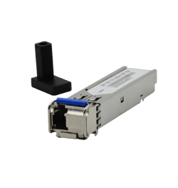
Optical transmitters are an important part of fiber optic network. They are converting and directing optical light through optical cables. They consist of two main parts, transmitter and receiver. When it comes to maintenance and troubleshooting, it is very important to be able to predict, test and find where a problem might occur or has already occurred. Sometimes if the connection does not reach the expected bit error ratio, we cannot tell at first glance which part of the connection is causing the problem. It may be the cable, the receiver, the receiver, or both. In general, the specification must ensure that any receiver will operate normally with any worst-case transmitter, and conversely that any transmitter will provide a signal of sufficient quality to be received by the worst-case receiver. Defining the worst metrics is often the hard part. However, there are generally four steps in testing the transmitter and receiver side of the receiver.
When it comes to testing the transmitter part, testing involves testing the wavelength and shape of the output signal. There are two steps to testing the transmitter:
The optical output of the transmitter should be tested with the help of several optical quality criteria such as mask test, optical modulation range (OMA).
Testing with an eye diagram is the most common method for viewing the transmitter waveform and providing information about the overall performance of the transmitter. In an eye diagram, all combinations of data patterns are superimposed on a common time axis, usually less than two bits wide.
Testing the receiving end is the more complicated part of the process, however there are two testing steps:
The first part of the test is to verify that the receiver can receive and convert the low quality signal. This is done by sending low quality optical light to the receiver. Since this is an optical signal, it must be calibrated using jitter and optical power measurements.
Another part of the test is the electrical input test of the receiver. At this stage, three sets of tests should be performed: the eye mask test to ensure that the eye is opened large enough, the shaking test
Some form factors, for example SFP+ receivers, define some important tests. These tests are critical and are shown in the table below:
| Test/Measurement | Recommended signal type | Threshold | |||
| Min. | Target | Max. | Unit | ||
| AC common mode voltage tolerance | PRBS31 | 15 | mV | ||
| Single-ended input voltage tolerance | PRBS31 | -0.3 | 4 | V | |
| Total jitter | PRBS31 | 0.28 | UI (p-p) | ||
| Output AC common-mode voltage | PRBS31 | 15 | mV | ||
| Data dependent jitter | PRBS9 | 0.1 | UI (p-p) | ||
| Uncorrelated jitter | PRBS9 | 0.023 | UI (RMS) | ||
| Eye-mask hit ratio | PRBS31 | X1= 0.12UI; X2= 0.33UI; Y1= 95mV; Y2= 350mV | |||
Fiber optic module testing is a complex and critical task to ensure that it is always working at peak performance. Even the most basic eye mask test is widely used today and is sufficient to ensure transmitter performance. Receiver testing is a more complex process, but testing using complex “stress” signals is becoming more common due to accurate results.
ماژول فیبر نوری چیس