0
0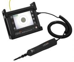
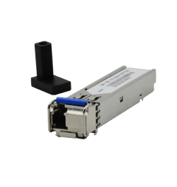
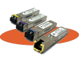
Optical patch cord quality
To provide high quality fiber patch cord, manufacturers perform a series of tests during the design and manufacturing stages. These fiber optic tests are critical to almost any type of fiber network. It is necessary not only for sellers, but also for end users to know what these tests are in order to know the quality of the fiber cable and then decide where they want to use it. In this post, three tests are introduced: 3D measurement, insertion loss (IL), return loss (RL), and end surface determination (smoothness and cleanliness), which assure end users that patch cord cables are They are of high quality.
1. 3D measurement: guarantee of final connection (connector connection) with high quality
3D measurement test or 3D surface measurement is a key test to control the performance of fiber optic connectors. In the production and operation of fiber optic cable components, the 3D interferometer plays an important role as a tool to perform optical interferometry so that vendors can check the fiber end surface and accurately control the end dimension. The three main features measured are radius of curvature, peak offset and core height.
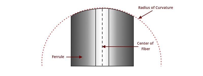
radius of curvature
As you can see in the picture below, the radius of curvature is the roundness of the end surface of the ferrule. The radius of curvature of the connecting surface of the high-quality fiber patch cable must be controlled within a certain range. Too much radius causes too much compression on the glass and too loose causes too much pressure on the surrounding ferrule and the compression of the glass is not enough. Too much or too little radius can cause light scattering or insufficient physical contact for optimal signal transmission. Only a proper radius allows proper compression and maximum performance.
Quality patch cord
Apex offset
It refers to the linear distance between the highest point of the end surface of the polished ferrule and the center of the fiber. This is a key term to reinforce during the polishing process. Incorrect payment can be one of the main reasons.
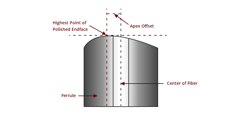
In theory, splices mated with center vertex offsets should have perfect core-to-core bonding without any air gaps. If there is a large offset peak, an air gap can be created, resulting in high IL and RL. Optical connectors with PC or UPC ferrules must set the zenith point at 0° vertical angle when paying. When the ferrule is completely perpendicular to the polished surface, the apex will be the exact center of the fiber. The APC ferrule is another case. The ferrule should be at an 8 degree angle to the fibers instead of being completely vertical. For more information on PC, UPC, and APC payment styles, see PC vs UPC vs APC Connector: Choosing the Right Fiber Connector Type.
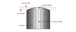
Fiber height
Core height is the height that the fiber core extends from the surface of the ferrule. The height of the core should not be too high or too low. If it is too high, the fiber may be damaged during splicing. If it is too small, a gap is created between the connected connection, thereby increasing the insertion (connection) loss. Especially for high volume transmission systems
Quality patchcord core length
Standard values vary across core modes and polishing styles, so specific products must meet or exceed industry-accepted end surface geometry standards. The diagram below shows the geometrical requirements for single-mode MTP trunk cable termination surfaces based on IEC/PAS 61755-3-31 and IEC/PAS 61755-3-32.
| Item | Suggested amount |
|---|---|
| Ferrule X angle (SX) | -0.2~0.2° (PC and APC) |
| Ferrule Y angle (SY) | ±0.2° |
| Ferrule X radius (RX) | ≥2000 mm |
| Ferrule Y radius (RY) | ≥5 mm |
| Fiber Curvature Radius (RF) | ≥1 mm |
| Fiber height (H) | 1000~3000 nm |
| Max fiber height diff (HA) | 500 nm |
| Max adjacent height diff (HB) | 300 nm |
| Coplanarity | ≤2000 nm |
| Core dip | -100nm~+200 nm |
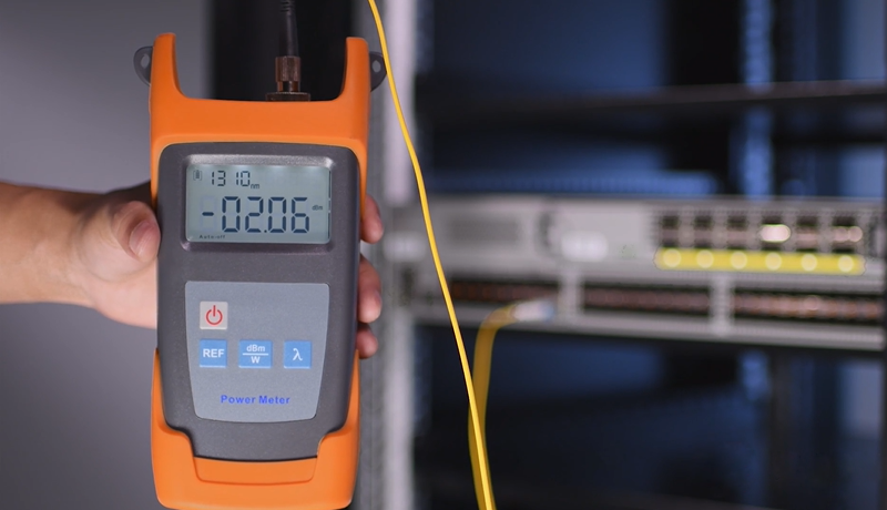
2. IL & RL Test: Vital for setting up the optical system
IL, or insertion loss, is the loss of signal strength caused by the insertion of a device into a transmission line or optical fiber. RL or return loss is the loss of signal power reflected back to the light source. In the reference Insertion Loss and Return Loss for Fiber Splices, definition of IL and RL, causes and tips for optimizing insertion/return loss values are introduced.
It doesn’t matter the manufacturing or installation process, IL & RL testing is of great importance. For optical cable vendors, the tested insertion loss and efficiency must comply with a series of relevant standards. For example, TIA standards specify a maximum fiber splice insertion loss of 0.75dB, which is considered the worst case. For most fiber connectors on the market, they range from 0.3dB to 0.5dB for standard loss and 0.15dB to 0.2dB for low loss. Manufacturers use IL/RL testers and meters to check whether the values are within normal limits so that end users can receive qualified products.
For end users, apart from taking the IL & RL value listed in the product specification list for reference for optical link design and selecting other devices and assemblies based on the reference value, you can also test by yourself. This helps installers to troubleshoot and identify faulty system components. OTDR, OFDR are techniques that are often used to measure return loss.
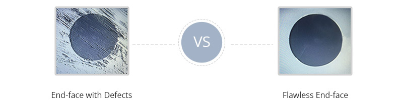
3. Ferrule clarity: necessary inspection to ensure the cleanliness of the connector
We’ve talked about cleaning many times, more specifically, cleaning the end of the connection. Final surface resolution is a fundamental method of maintaining fiber optics, both 40 years ago and today. Manufacturers perform a surface inspection to ensure there is no contamination, scratches, or cracks on the end surface of the joint. Almost every fiber optic engineer has fiber optic testers/cleaning tools such as pen cleaners or cassette cleaners that are often seen when installing cables.
Microscope connector
Why is endface transparency important? The cleanliness and smoothness of the optical fiber connection interface is one of the basic and important measures to maintain the quality of optical fiber connections. It is different from any other type of cleaning due to the deformation at the end of the connector and the particulate contaminants are on it. Even microscopic dust can increase return losses and even cause permanent damage to connections. In addition, dust between the two ends of the surface can scratch the surface and cause air gaps or mismatches between the fiber cores, which degrades the optical signal. Since these contaminations are very small to see without a microscope, if you pair a dirty branch, the other branch can also be infected. Therefore, even if the vendors have done the endface transparency during fiber optic connection testing, you should be diligent in checking and cleaning the end faces every time before connecting the connectors or after the connectors are unpaired. More information on connector cleaning is in this post: How Much Do You Know About Fiber Connector Cleaning?
In summary, the fiber optic industry improves the quality of fiber connection by reviewing the main parameters to be measured and industry associations and committees to define fiber quality assurance manufacturing criteria. If the fiber patch cables pass the above three tests and the test results meet the standards, they are able to contribute to high-quality optical transmission. For end users, it is necessary to check whether the vendors perform these tests and confirm the test parameters with these provided test reports.
All optical fiber patch cords produced in Arivant are tested according to international standards.