0
0Insertion Loss and Return Loss in optical fiber
As we know, a large number of fiber optic cables are used in optical communication between devices, and the optical connectors of fiber cables are required to be reliable for high-performance fiber optic networks. Insertion loss (IL) and return loss (RL) are two essential parameter measurements when measuring the attenuation effects of fiber joints.
What is Insertion Loss and Return Loss for fiber connections?
What is power loss?
In telecommunications, power loss is the loss of signal strength, calculated as a ratio in decibels (dB) and the result of placing a transmitter or source at the beginning and a measuring device at the end of the line. transmission or optical fiber. It can also be referred to as attenuation, which shows how much the signal drops by comparing the input power to the output power. The lower this number is, the better. For example, 0.3dB insertion loss is better than 0.5dB.
What is return loss?
When a signal is transmitted over a transmission line, due to the discontinuity of the transmission line, some of the signal power is always reflected or returned to the source. The discontinuity can be a mismatch with the load of the terminator or the device that is placed in the line. Return loss refers to the power loss of the reflected signal. Therefore, the higher the return loss, the lower the reflection rate. In other words, the fiber connection with higher RL value will perform better.
What factors cause power loss and loss of light return?
Ideally, if the fiber patch cable has no splices, minimal loss is achieved – a continuous, straight glass fiber from point A to point B without interruption. However, fiber optic networks require connections to be established. The performance of low IL and high RL is reduced due to the following three factors:
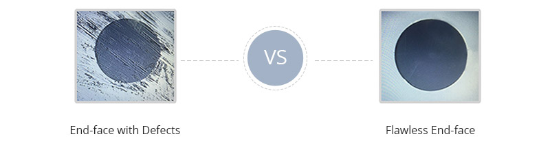
The quality and cleanliness of the connectors
Obviously, fiber end defects such as scratches, pits, cracks and particle contamination will directly affect performance and contribute to poor power/poor restoration. Any irregularity that hinders the transmission of light from one fiber to another will negatively affect IL and RL.
Microscope connector
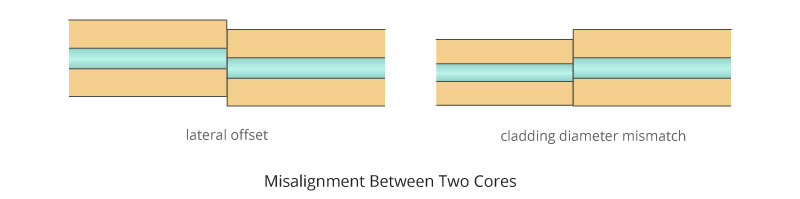
Lack of alignment (adaptation) between two blinds
The main function of the connector is to keep the blinds precisely aligned in place, ensuring that the core of one fiber is precisely and precisely aligned with the core of another fiber, thus making every connector with Another connection is coupled with precise core-to-core alignment – core contact. Typically, the smaller the diameter of the ferrule hole, the more precisely the fiber will fit into the ferrule. If the ferrule hole is not perfectly centered, the blinds that are held in it will never be perfectly centered and aligned. Therefore, a mismatch between the two cores often occurs when the blinds with the light-carrying cores do not perfectly match each other, resulting in poor IL/RL.
Fiber blind alignment
Poor bit connection between connector and core
In order to achieve low IL and high RL, optimized core-to-core contact must be achieved and maintained. Different polishing styles of fiber splices have core-to-core contact performance in terms of splice loss and splice loss. Usually, the loss of PC, UPC and APC connectors is less than 0.3dB. However, UPC connectors have the lowest IL due to the smallest air gap, while APC connectors have the highest RL due to the diagonal fiber end faces. The difference between PC and UPC and APC connectors will help you choose the right type of fiber connector.
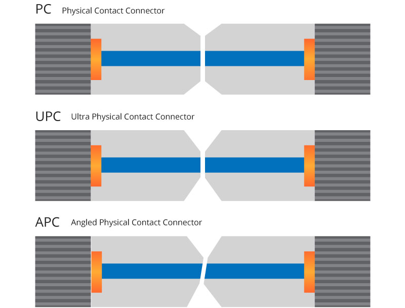
The difference between the UPC and APC connectors
How to reduce the loss of fiber connections?
The use of tested and high-quality connectors helps network users to have high-speed connections that perform well in the long term. Here are some tips for optimizing power loss and return loss:
Keep all fiber connections clean, especially before and after installation and testing. Using the appropriate tool to clean the connector joints.
Minimize the number of complex bends, joints and connections that may cause light to refract through the blind cover. If you need to bundle the fiber, keep the radius as large as possible.
Use cables produced by well-known factories. These companies follow strict instructions and usually include a guarantee.
Arivant has a comprehensive laboratory for testing and measuring all parameters.